|
How to connect an EPSON P300017100 LCD to your PC with a SED1330 LCD driver IC
This page contains informations about electronical devices and informations
help you build an LCD driver ISA-bus card for your PC. You should note that THE
AUTHOR of this page REFUSES ANY RESPONSIBILITY! This page and informations you
find on it comes with ABSOLUTELY NO WARRANTY! Building this card can cause
damage to your computer! Any damages to your computer or any harmful things
happen to you is your responsibilty! If you don't agree with it you'd better
leave this page now (click 'BACK' on your browser).
Here you can find informations about an LCD and an ISA card (built by me) for
using this LCD. The card uses EPSON's SED1330, but the card is not 100%. I mean
the following: you can send data to SED1330 (and to it's display memory), but
you can't read back any data! I'm sure, that this is somekind of a timeing
problem, however it wasn't necessary for me to read back any information from
the display memory or from the SED1330's registers... so keep it in mind: this
is a "one-way" card. Since this is FREE, I take NO SUPPORT. The card is not
copyrighted, but I expect that no one use it to make money from it! Please do
not write me letters about buying components (I can't help you buying LCDs,
driver ICs). Also, do not write me letters, that the card you've built according
to my informations is not working! (My card works perfectly, I've tested it with
a 386DX40, 5x86P75, IP233MMX, ICeleron433 system). After all, I'm looking for
comments and letters about successfully working LCD cards...
Good luck, David Toth (dave@iris.elte.hu)
The EPSON P300017100 LCD
First, a picture taken from the LCD:
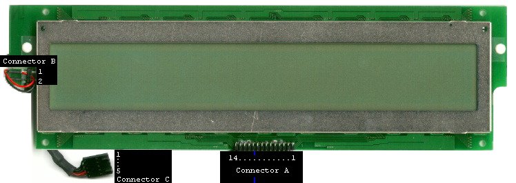
EPSON P300017100 is a passive 512x64 dot-matrix LCD with backlight. On the
back side of the LCD panel (not shown) you found 8x SED1180 and 1x SED1190 ICs (you
can download documentation about SED1180 from here
and SED1190 from here).
For SED1330 users: the panel needs single-panel drive, 16-line AC drive.
Pinouts:
| 'Connector A' |
Connected on the LCD panel to |
| Pin 1: Vcc (+5V DC) |
SED1180 pin 73 (Vdd), SED1190 pin 74 (Vdd) |
| Pin 2: GND |
SED1180 pin 72 (Vss), SED1190 pin 75 (Vss) |
| Pin 3: Contrast Voltage* |
pins (of SED1180 and SED1190 thru resistors): Vssh, V2,
V3. |
| Pin 4: LP |
SED1180 pin 35 (LP), SED1190 pin 80 (YSCL) |
| Pin 5: WF |
SED1180 pin 36 (FR), SED1190 pin 79 (FR) |
| Pin 6: YDIS |
SED1190 pin 78 (-INH) |
| Pin 7: YSCL |
SED1190 pin 77 (LAT) |
| Pin 8: YD |
SED1190 pin 76 (DI) |
| Pin 9: XSCL |
SED1180 pin 34 (XSCL) |
| Pin 10: XECL |
SED1180 pin 76 (ECL) |
| Pin 11: XD0 |
SED1180 pin 33 (D0) |
| Pin 12: XD1 |
SED1180 pin 32 (D1) |
| Pin 13: XD2 |
SED1180 pin 31 (D2) |
| Pin 14: XD3 |
SED1180 pin 30 (D3) |
(Note: the pinout is according to SED1330's connections!)
'Connector B'
Pin 1: Backlight voltage**
Pin 2: Backlight voltage**
'Connector C'
Pin 1: ?
Pin 2: Backlight voltage**
Pin 3: GND
Pin 4: Backlight voltage**
Pin 5: ?
*The contrast voltage is NEGATIVE DC voltage (e.g. -12V ... 0V).
**The backlight voltage is nearly 100V AC! I am using here a DC/AC converter which
converts 0...6V DC to 0..100V sinus AC.
Notes for the LCD:
I used a SED1330 LCD driver IC to use the
display. 'Connector A' pins 4 to 14 can be connected directly to this driver IC
(SED1330). 'Connector B' is not a connector, infact it's the power supply pins
for the backlight. 'Connector B' pin 1 and 2 are connected to a wire at one end
and on the other end of the wire is 'Connector C'. 'Connector C' pin 2 and pin 4
is the backlight power supply (these are the red and black wire at 'Connector
B'), pin 3 is the shield for the cable. 'Connector C' pin 1 and pin 5 connected
together (but not connected to pin 3). I think these two pins are GND, too.
I think the backlight is 'optional', because it can be removed easily
(you can remove it: unlock the two white plastic lock at the edges of the LCD
and remove the black plastic-ring. Now you can pull the lightsource from the
LCD. Ofcoz' you can put the whole thing back, except the black plastic-ring.)
Mine produces somekind of 'blue' light.
A "one way" SED1330 based ISA card
This card makes possible the communication between your PC's CPU and
the SED1330 LCD driver IC (which has the LCD connected to). The "one way" means
that your PC's CPU can send data to SED1330, but can't receive! If you need to
read back data from the SED1330, do not build this card, this card won't do.
You can check it's schematics clicking here.
I'm sorry but I've lost the original schematics file, the picture you see is a scanning of the
original schematics printed version...
About the card: U1 (74132)
watches /IOR and /IOW on the bus. If one of them is active (these pins are
active-low) U1 enables the two comparators (U2, U3). U1 also generates RESET
signal for SED1330. U2 and U3 (74520) make comprehension between the address on
the bus and the address set on J1. Only addresses 0-0x3FE can be set to the card
(as it's address). U2 also takes care about /AEN (if it is not low, DMA uses the
bus). U7 (7432) takes care about the two comparators output. If the addresses
are equal (and /AEN low) there is data on the bus for the card, U7 (OR-gate)
enables SED1330 and U4 (74245 bus driver). U6 is a 32Kbyte static ram, used for
SED1330's display memory.
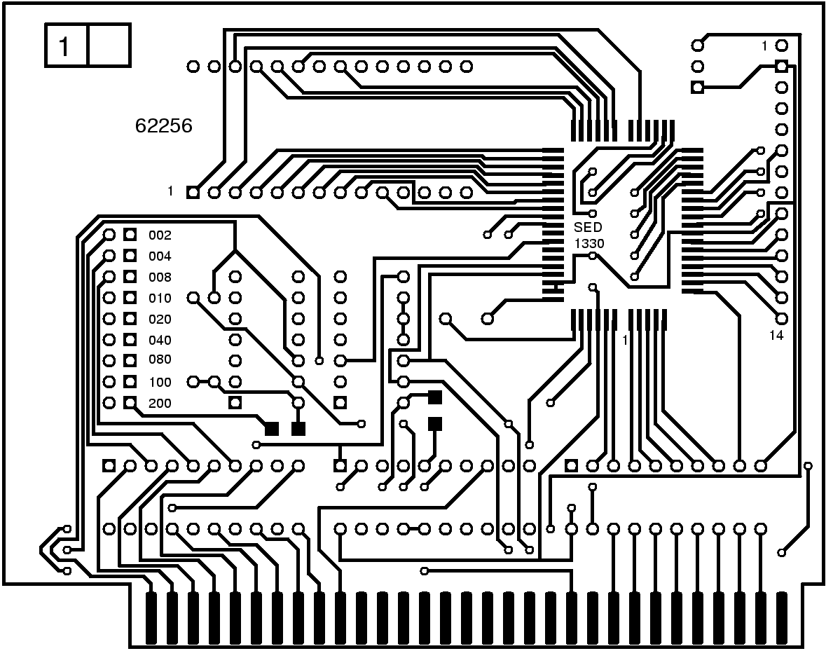
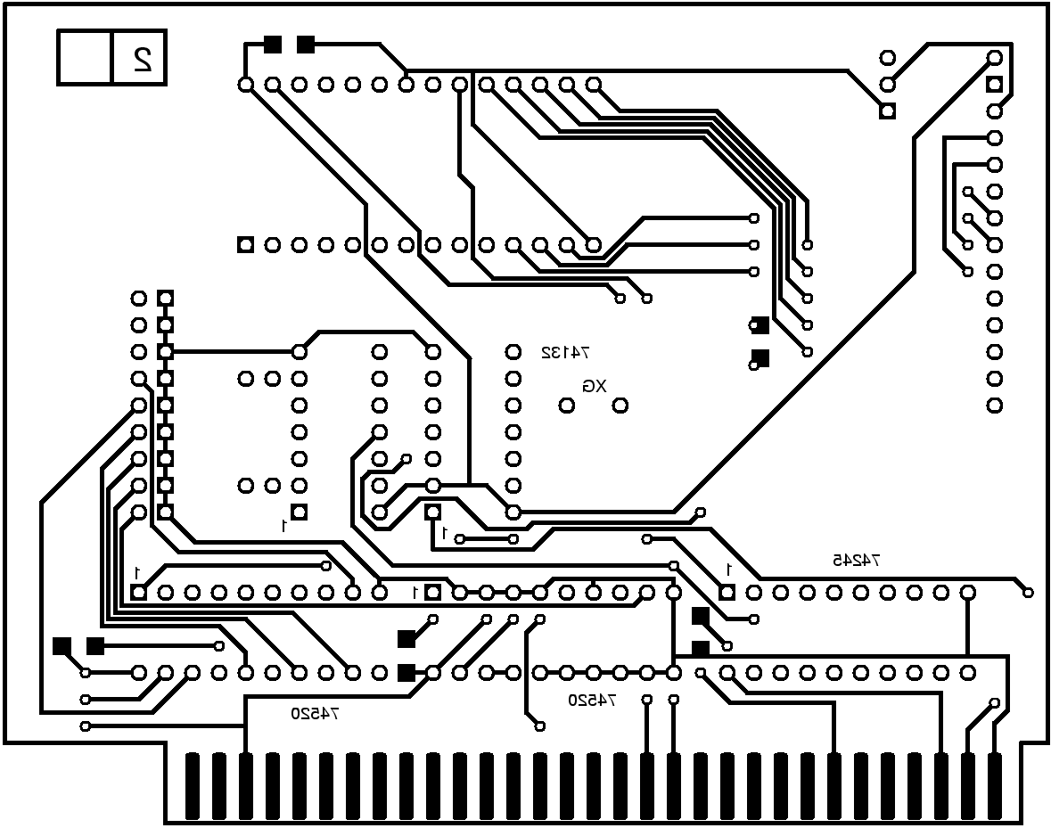
You can see two pictures taken from my card:
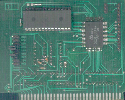
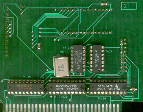
This is a bit differ from the card described
below, becuase in the beginning I used 74ALS32 on my card, but that was too slow
(when I sent data to the card and sent another data to a different address the
card used the 'another data', too..) So I replaced it with 74HC32, but this
change made necessesry two pull-up resistors. Since, the panel was ready and I
didn't want to build a new card, I put the two resistors in the circuit in a way
you see on these pictures. If you build this card you can download a PCB file
for it later. Of course, I've modified the PCB for these resistors.
Do you want to build it?
Be sure, that your LCD can be driven with SED1330 before you begin to build it.
(e.g. you also have a 14 pinout on your LCD and you see SED1180(s) and SED1190(s) on it).
You should have experience in making printed circuits, and a small experience in C programming!
If you have, read it carefully:
1. If you don't know what is SED1330, you can download a PDF file about SED1330/SED1335/SED1336
clicking here.
2. Buy it's components. SED1330Fba is hard to get, but maybe you also have one:)
Anyway, here is a list about components you need:
- SED1330Fba.
- 62256 (32Kbyte static RAM)
- 2x 74520 (You can also use 74522 and 74689. These three ICs are equivalents. I used 74(ALS)522.)
- 1x 74245 (Bidirectional bus driver. I used 74HC245).
- 1x 74HC132
- 1x 74HC32 (do not use ALS here!)
- 2x 10kOhm pull-up resistors (not SMD. for 74HC32)
- 7x 100nF SMD capacitor
- 6MHz oscillator (or any less than 10MHz. also read page 52
in the SED1330 PDF you've just downloaded)
- 14 pinout
- 3 pinout + 3pin connector (if you want to change the contrast anytime)
- 10kOhm potmeter (for contrast)
- 2x 9 connector
- 9 jumpers (for the 2x9 connector)
- the printed circuit. You can download it's PCB file by
clicking here.
The layout is two sided and for SED1330Fba only. There are companies make you the
circuit on the basis of this PCB file. Since I've received letters about
problems with opening this PCB file, I've converted the PCB file into Adobe
Encapsulated PostScript and BMP files.
Here they are:
(To convert from PS to BMP I've used ImageMagic, the command: convert -density 300x300,
so the BMP's are 300pixel/inch)
But remember: using the PCB file you can make more accurate circuit layouts and photomasks than using BMPs.
3. Place the components on the board. Use these two pictures:
Note: 100nF capacitors are not shown on the schematics but they are on the board! ('C' components)
10kOhm potmeter is for contrast set. Connect it to the 3 pinout (J3) as follows:
pin 1 ----[=====]---- pin 3
^--------- pin 2
4. Set the card address as follows: decide what address you want
to use (and check it's not used, yet! For a little help do NOT use the
followings (according to IBM-AT map): 0x000-0x1F8, 0x200-0x207, 0x20C-0x20D,
0x21F, 0x278-0x27F, 0x2B0-0x2DF, 0x2E2-0x2E3, 0x2F8-0x31F, 0x360-0x36F,
0x378-0x393, 0x3A0-0x3DF, 0x3F0-0x3FF), for an example now we choose 0x34E.
Substract it from 0x3FE, which is (0x3FE-0x34E=) 0xB0. J1 has text on the board.
Put jumpers on the pins next to 0x80, 0x20, 0x10 (because 0xB0=0x80+0x20+0x10.
See my card. That is also set to 0x34E) and leave the others open.
5. Insert it to an empty ISA slot in your computer. Make
sure that J2 and J3 is closer to the back of your computer than J1 - an even
better rule: the ISA connector has more pinouts the card not uses. These pinouts
should be at the "address set jumpers" side of the panel (that is the right
direction to put the card into an ISA slot in your computer. Do not insert the
card in the wrong direction since this could cause serious damage). Connect
contrast potmeter, connect LCD to the card.
6. Download
the following C program (for MS-DOS) to try out your card (and also your LCD).
To compile the source code I recommend you to use DJGPP. You can also download a precompiled
binary of the source code above
(if the exe fails to run with the error message "Load error : no DPMI"
extract this cwsdpmi
into any directory which is in your path - or into the directory the exe situated).
Run the exe with the following arguments: sed.exe -p0x34e -t1 -tt0x34c
(0x34e is the address of the
card; 0x34c is an address not used by any resources in your computer). Press 'y'
and if you see vertical columns on your LCD (and a text message flashing) you
can be happy... (if not, see troubleshoot). Pressing enter the program sends new
data to the display memory (which is not changes for this time). Pressing 'q'
the program quits.
(You can also try out if your card responses only for it's address with
sed.exe -p0x34e -t2 -tt0x34c but if -t1 fails, -t2 fails too...).
Now start sed.exe -p0x34e. You
should see text messages (on the right of the panel text have to flash, on the
left another text with bigger charset) and lines. Pressing enter the lines
change position...
Notes: you should
know: the ISA bus's A0 is connected to SED's A0. This means that if you want to
send a command to SED, send it to it's port address +1 (e.g. 0x34F if you follow
my settings), and send data to it's port address (0x34E). Check the source code
(especially init_lcd() there are the parameters for P300017100) and feel free to
modify it... also check the PDF file, there is everything you need to know about SED1330.
Troubleshoot
1. There's nothing on my LCD while sed.exe is running. Check your LCD's
type (if it is differ from P300017100 you have to change the source code you've
downloaded, especially init_lcd(), WINWIDTH, WINHEIGHT). Check contrast. Check
if your LCD is connected to the card. Check your card, it's direction, and
components on it (you have all the components on it?).
2. Starting sed.exe using the switch -t1 I see something 'stairway'-like pattern on
LCD or using the switch -t2 I see 'chaos' on the screen or after I put the card
into my computer hardwares work wrong (e.g. your Disk Drive is reading 'dummy'
data or fails): your card responses for other addresses than it's. Check if you
are using 74HC32 (important), and the pull-up resistors are on board!
|
