
|
|
Based on the David Toth page |
|
NIKOMP S.C. - ul. 3 Maja 19, PL 40-097 Katowice,
tel: +48 (32) 206 27 94, fax: +48 (32) 253 07 00,
e-mail: sklep@nikomp.com.pl Elementy elektroniczne - handel detaliczny i hurtowy / Electronic components - retail and wholesale |
|
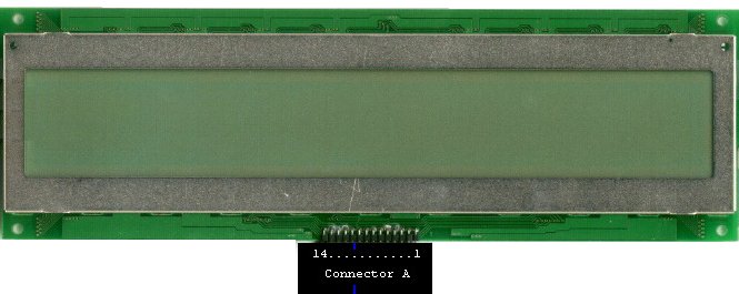
How to connect an EPSON P300008111 LCD to your PC with a SED1330 LCD driver IC This page contains informations about electronical devices and informations help you build an LCD driver ISA-bus card for your PC. You should note that THE AUTHOR of this page REFUSES ANY RESPONSIBILITY! This page and informations you find on it comes with ABSOLUTELY NO WARRANTY! Building this card can cause damage to your computer! Any damages to your computer or any harmful things happen to you is your responsibilty! If you don't agree with it you'd better leave this page now (click 'BACK' on your browser). Here you can find informations about an LCD and an ISA card (built by me) for using this LCD. The card uses EPSON's SED1330, but the card is not 100%. I mean the following: you can send data to SED1330 (and to it's display memory), but you can't read back any data! I'm sure, that this is somekind of a timeing problem, however it wasn't necessary for me to read back any information from the display memory or from the SED1330's registers... so keep it in mind: this is a "one-way" card. Since this is FREE, I take NO SUPPORT. The card is not copyrighted, but I expect that no one use it to make money from it! Please do not write me letters about buying components (I can't help you buying LCDs, driver ICs). Also, do not write me letters, that the card you've built according to my informations is not working! (My card works perfectly, I've tested it with a 386DX40, 5x86P75, IP233MMX, ICeleron433 system). After all, I'm looking for comments and letters about successfully working LCD cards... Good luck, David Toth (dave@iris.elte.hu) The EPSON P300008111 LCD First, a picture taken from the LCD:
EPSON P300017100 is a passive 512x64 dot-matrix LCD without backlight. On the
back side of the LCD panel (not shown) you found 8x SED1180 and 1x SED1190 ICs (you
can download documentation about SED1180 from here
and SED1190 from here).
For SED1330 users: the panel needs single-panel drive, 16-line AC drive.
*The contrast voltage is NEGATIVE DC voltage (e.g. -12V ... 0V). Notes for the LCD: I used a SED1330 LCD driver IC to use the display. 'Connector A' pins 4 to 14 can be connected directly to this driver IC (SED1330). A "one way" SED1330 based ISA card This card makes possible the communication between your PC's CPU and
the SED1330 LCD driver IC (which has the LCD connected to). The "one way" means
that your PC's CPU can send data to SED1330, but can't receive! If you need to
read back data from the SED1330, do not build this card, this card won't do.
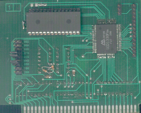
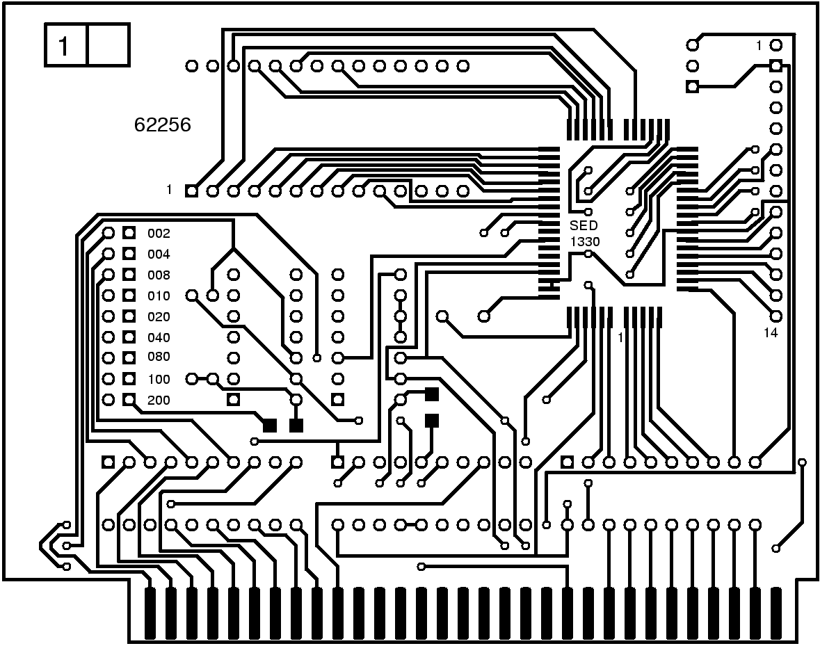
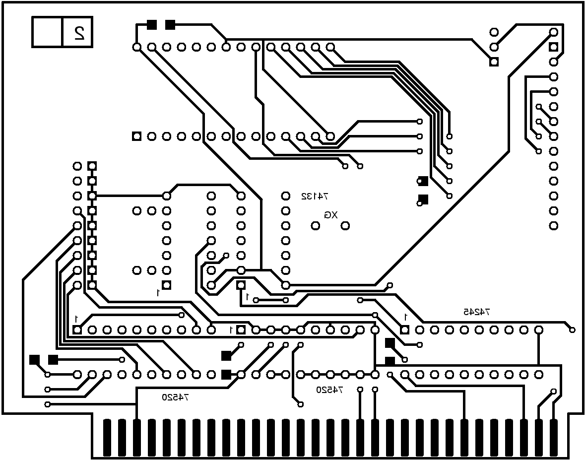
This is a bit differ from the card described below, becuase in the beginning I used 74ALS32 on my card, but that was too slow (when I sent data to the card and sent another data to a different address the card used the 'another data', too..) So I replaced it with 74HC32, but this change made necessesry two pull-up resistors. Since, the panel was ready and I didn't want to build a new card, I put the two resistors in the circuit in a way you see on these pictures. If you build this card you can download a PCB file for it later. Of course, I've modified the PCB for these resistors. Do you want to build it? Be sure, that your LCD can be driven with SED1330 before you begin to build it.
(e.g. you also have a 14 pinout on your LCD and you see SED1180(s) and SED1190(s) on it).
1. If you don't know what is SED1330, you can download a PDF file about SED1330/SED1335/SED1336 clicking here. 2. Buy it's components. SED1330Fba is hard to get, but maybe you also have one:)
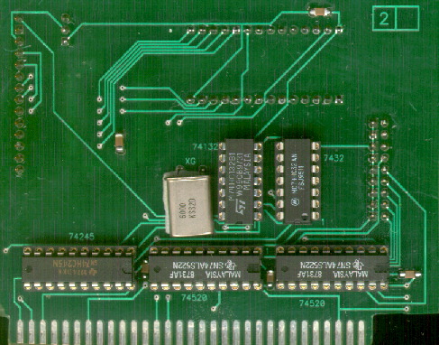
But remember: using the PCB file you can make more accurate circuit layouts and photomasks than using BMPs. 3. Place the components on the board. Use these two pictures:
Note: 100nF capacitors are not shown on the schematics but they are on the board! ('C' components)
4. Set the card address as follows: decide what address you want to use (and check it's not used, yet! For a little help do NOT use the followings (according to IBM-AT map): 0x000-0x1F8, 0x200-0x207, 0x20C-0x20D, 0x21F, 0x278-0x27F, 0x2B0-0x2DF, 0x2E2-0x2E3, 0x2F8-0x31F, 0x360-0x36F, 0x378-0x393, 0x3A0-0x3DF, 0x3F0-0x3FF), for an example now we choose 0x34E. Substract it from 0x3FE, which is (0x3FE-0x34E=) 0xB0. J1 has text on the board. Put jumpers on the pins next to 0x80, 0x20, 0x10 (because 0xB0=0x80+0x20+0x10. See my card. That is also set to 0x34E) and leave the others open. 5. Insert it to an empty ISA slot in your computer. Make sure that J2 and J3 is closer to the back of your computer than J1 - an even better rule: the ISA connector has more pinouts the card not uses. These pinouts should be at the "address set jumpers" side of the panel (that is the right direction to put the card into an ISA slot in your computer. Do not insert the card in the wrong direction since this could cause serious damage). Connect contrast potmeter, connect LCD to the card. 6. Download
the following C program (for MS-DOS) to try out your card (and also your LCD).
Troubleshoot 1. There's nothing on my LCD while sed.exe is running. Check your LCD's
type (if it is differ from P300017100 you have to change the source code you've
downloaded, especially init_lcd(), WINWIDTH, WINHEIGHT). Check contrast. Check
if your LCD is connected to the card. Check your card, it's direction, and
components on it (you have all the components on it?).
|